
OPGW-24 G.652 ULL, factory-direct supply to European utilities
Model OPGW-24G652-2S-111. 24 G.652 ultra-low-loss fibers in a stainless-steel central tube. 71.0 kN rated tensile strength. 92.52 kA²S short-circuit current capacity. IEC 60794-4-10 and IEEE 1138-2009 compliant. Replaces conventional earth wire on 110–500 kV transmission lines, delivering grounding, lightning protection, and a 24-fiber optical backbone in a single cable.
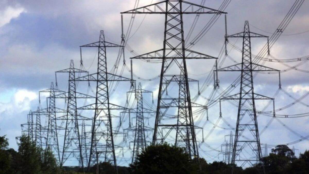
One cable doing three jobs on every transmission span
Every high-voltage overhead power line already carries a ground wire above the phase conductors. That wire's job is to intercept lightning strikes and provide a low-impedance return path for fault current. It carries no data, it never has.
OPGW replaces that earth wire with a composite cable that performs the same electrical functions, lightning shielding, fault current grounding, while housing an optical fiber backbone inside a stainless-steel central tube. The OPGW-24G652-2S-111 adds 24 G.652 ULL single-mode fibers to a span that previously carried none, with no change to tower attachment hardware and no additional mechanical loading on the structure.
For transmission system operators, that fiber backbone enables real-time SCADA, protection relay signaling, synchrophasor networks, and leasable telecom capacity, all from a cable that had to be there anyway.
Full cable and fiber data, OPGW-24G652-2S-111
Cable structure
Centre and Layer 1 are greased. Outer layer stranding direction is right-hand (Z-stranding). Designed and manufactured per IEC and IEEE standards.
| Layer | Material | Qty | Contents | Fiber qty | Diameter |
|---|---|---|---|---|---|
| Centre | 20.3% AS (aluminium-clad steel) wire | 1 | — | — | 2.80 mm |
| Layer 1 | 20.3% AS wire | 5 | — | — | 2.80 mm |
| Layer 1 | SUS stainless-steel tube | 1 | All 24 G.652 ULL fibers | 24 | 2.80 mm |
| Layer 2 | AA (aluminium-alloy) wire | 12 | — | — | 2.80 mm |
Mechanical and electrical data
| Parameter | Unit | Value |
|---|---|---|
| Cable diameter | mm | 14.00 |
| Cable weight | kg/km | 465 |
| Supporting cross section | mm² | 110.8 |
| Section of AS wire | mm² | 36.95 |
| Section of AA wire | mm² | 73.89 |
| Rated Tensile Strength (RTS) | kN | 71.0 |
| Modulus of Elasticity (E-Modulus) | kN/mm² | 97.3 |
| Thermal Elongation Coefficient | ×10⁻⁶ /°C | 17.5 |
| Permissible Max Working Stress (40% RTS) | N/mm² | 256.4 |
| Everyday Stress, EDS (16–25% RTS) | N/mm² | 102.6 – 160.3 |
| DC Resistance | Ω/km | 0.379 |
| Short-time current (1 s, 20°C → 160°C) | kA | 9.6 |
| Short-time current capacity I²t | kA²S | 92.52 |
Bending radius and temperature limits
| Parameter | Condition | Value |
|---|---|---|
| Minimum bending radius | Installation | 280 mm |
| Minimum bending radius | Operating (in service) | 210 mm |
| Temperature range | Installation | −10°C to +50°C |
| Temperature range | Transport & operation | −40°C to +85°C |
G.652 ULL optical fiber, in-cable performance
Ultra-low-loss G.652 fibers in a stainless-steel hermetic tube. PMD controlled using spun fiber technology during cabling.
| Category | Parameter | Unit | Specification |
|---|---|---|---|
| Optical | Attenuation @ 1310 nm | dB/km | ≤0.31 |
| Attenuation @ 1550 nm | dB/km | ≤0.18 | |
| Zero dispersion wavelength | nm | 1300–1324 | |
| Zero dispersion slope | ps/nm²·km | ≤0.092 | |
| PMD link value | ps/√km | ≤0.2 | |
| Cable cutoff wavelength (λcc) | nm | ≤1260 | |
| Macro bending loss (100 turns, Ø50 mm) @ 1550 nm | dB | ≤0.05 | |
| Macro bending loss (100 turns, Ø50 mm) @ 1625 nm | dB | ≤0.10 | |
| Mode field diameter @ 1310 nm | µm | 9.2 ± 0.4 | |
| Dimensional | Cladding diameter | µm | 125 ± 1.0 |
| Core/clad concentricity error | µm | ≤0.6 | |
| Cladding non-circularity | % | ≤1 | |
| Mechanical | Proof stress | GPa | ≥0.69 |
Drum specifications
OPGW shipped on non-returnable wooden drums. Both ends sealed with shrinkable caps. Weatherproof marking per customer requirements.
| Drum length (m) | Flange Ø D (cm) | Traverse b (cm) | Overall B (cm) | Barrel Ø d (cm) | Drum weight (kg) |
|---|---|---|---|---|---|
| 2,000 | 130 | 90 | 110 | 80 | 190 |
| 3,000 | 140 | 90 | 110 | 80 | 200 |
| 4,000 | 150 | 90 | 110 | 80 | 230 |
| 5,000 | 160 | 90 | 110 | 80 | 260 |
Cable structure, optical specs, mechanical data, electrical characteristics, test procedures, drum dimensions
Three-tier testing: Routine, FAT, and Type tests
Three independent test series cover OPGW quality from production through commissioning. Routine tests run in-process during manufacturing. Factory Acceptance Tests (FAT) are performed on the finished cable at the factory, customer or inspector witness attendance can be arranged. Type tests qualify the design for field service and can be satisfied by submitting existing certificates from an internationally accredited independent laboratory.
Routine tests
- OTDR attenuation, all 24 fibers per IEC 60793-1-40
- Cable surface quality, lay direction, lay length
- Cable diameter and weight verification
- Wire: diameter, tensile strength, conductivity, elongation
- ACS wire: stress at 1% extension, torsion, Al-cladding thickness
Factory Acceptance Tests (FAT)
- OTDR attenuation, all fibers (customer witness)
- Breaking strength test per IEC 60794-4-10
- DC resistance measurement
- Full dimensional verification: diameter, weight, lay
- All wire tests (FAT scope)
Type tests (design qualification)
- Stress-strain, tensile performance, sheave test
- Aeolian vibration simulation and galloping test
- Short-circuit current test and lightning test
- Temperature cycle test and creep test
- Water penetration test
Where OPGW is specified, and why 24 fibers
Transmission system operators & utilities
TSOs and network operators replacing ageing earth wires specify OPGW for simultaneous grounding upgrade and fiber deployment. The 24-fiber count provides enough capacity for internal protection and SCADA communications while leaving commercially leasable spare capacity.
- SCADA and energy management systems
- Differential protection relay signaling
- Synchrophasor (PMU) data backhaul
- Inter-substation voice and operations comms
Telecom leasing and wholesale backhaul
Utilities with OPGW corridors lease spare fibers to mobile network operators, ISPs, and internet exchanges as regional and long-haul backhaul. A 24-fiber OPGW typically leaves 18+ fibers available after internal use, generating revenue from an asset that had to be installed anyway.
- Leased dark fiber for mobile backhaul
- IRU agreements with fixed-line carriers
- Point-of-presence connectivity for data centres
- Regional ring network diversity routing
Smart grid and grid modernisation
IEC 61850 station automation, advanced metering infrastructure backhaul, and dynamic line rating all require low-latency, high-reliability fiber links between substations and control centres. OPGW provides the physical layer for grid digitisation without additional tower attachments.
- IEC 61850 substation automation networks
- AMI (smart meter) data concentration backhaul
- Dynamic line rating sensor data transport
- EV charging infrastructure monitoring
Railways, pipelines, and linear infrastructure
Railway infrastructure managers and pipeline operators with overhead power facilities use OPGW on traction power lines to simultaneously upgrade the earthing system and deploy fiber for train control, ETCS, and SCADA systems along the corridor.
- Railway traction power line fiber backbone
- ETCS Level 2 and GSM-R backhaul
- Pipeline SCADA and cathodic protection monitoring
- Linear asset management network infrastructure
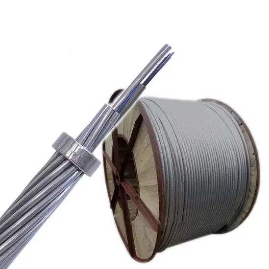
OPGW-24G652-2S-111 is shipped on non-returnable wooden drums in standard lengths of 2,000 to 5,000 metres, with both cable ends sealed with shrinkable caps. Drum lengths are selected to match span calculations and minimise mid-span joints, custom lengths can be accommodated at order stage.
Grid modernisation is the dominant OPGW procurement driver in Europe
European transmission and distribution operators are accelerating OPGW installation across three convergent pressures: ageing earth wire replacement programmes, the fiber infrastructure requirements of IEC 61850 substation automation, and the grid monitoring demands of large-scale renewable integration. The European Commission's grid action plan targets 600 GW of offshore and onshore renewable capacity by 2030, a build-out that requires a matching upgrade to the substation communication and protection infrastructure that OPGW enables.
OPGW procurement for European utility projects has traditionally been dominated by a small number of European and Japanese cable manufacturers selling through long-established utility supply frameworks. Factory-direct sourcing from ISO 9001-certified Chinese manufacturers, with full IEC 60794-4-10 and IEEE 1138 type test documentation, provides access to the same product quality at factory-gate pricing, outside the framework contract structure.
For project procurement teams, the key differentiator is documentation completeness: type test certificates, routine test records per drum, OTDR traces, FAT certificates, and CE-equivalent conformity documentation. We coordinate the full technical file from the factory as part of every OPGW order.
Enquire about your project →OPGW procurement, frequently asked questions
What is OPGW and how does it differ from conventional overhead ground wire?
OPGW (Optical Ground Wire) is a composite overhead cable that replaces the conventional earth wire on a high-voltage transmission line. Like a standard ground wire, it provides lightning protection and fault current grounding. Unlike a standard earth wire, OPGW contains an optical fiber unit, in the OPGW-24G652-2S-111, 24 G.652 ULL single-mode fibers in a stainless-steel hermetic central tube, enabling SCADA communications, protection relay signaling, synchrophasor data, and commercially leasable telecom capacity. OPGW installs in the same tower attachment position as the earth wire it replaces, with no additional hardware and no change to the line geometry below.
What standards does the OPGW-24G652-2S-111 comply with?
The cable is designed and manufactured to IEC 60794-4-10 (family specification for OPGW on power lines) and IEEE 1138-2009 (testing and performance standard for utility OPGW). The G.652 ULL optical fibers comply with ITU-T G.652. Wire components comply with IEC 61232 (aluminium-clad steel) and IEC 60104 (aluminium-alloy wire). Fiber color coding follows EIA/TIA 598 B. Full type test certificates from independent accredited laboratories are available and can be provided to satisfy tender documentation requirements.
Why is 24 fibers the right count for most utility OPGW projects?
24 fibers balances internal utility communications needs with leasable commercial capacity. A typical utility uses 4–6 fibers for protection relaying, SCADA, and operational voice. A 24-fiber OPGW leaves 18 or more fibers for commercial leasing to mobile operators, ISPs, or internet exchanges, generating revenue from the transmission corridor. Going above 24 adds cable weight and cost without meaningful additional utility capacity. 24 is the most commonly specified count in European TSO and DNO OPGW tenders and provides forward headroom for network growth and 5G backhaul leasing.
How is Factory Acceptance Testing coordinated for OPGW orders?
FAT is performed at the manufacturing facility before shipment. The scope for OPGW-24G652-2S-111 includes: OTDR attenuation on all 24 fibers per IEC 60793-1-40; breaking strength test; DC resistance; and full dimensional verification (diameter, weight, lay length, lay direction). Customer or independent inspector witness attendance at FAT can be arranged. Type test certificates covering aeolian vibration, galloping, short-circuit current, lightning, temperature cycling, and creep are available from prior qualification testing, these can be submitted in lieu of repeat type tests, as permitted under IEC 60794-4-10.
What drum lengths and delivery lead times apply?
OPGW-24G652-2S-111 is available on non-returnable wooden drums in standard lengths of 2,000 m, 3,000 m, 4,000 m, and 5,000 m. Custom drum lengths to match span calculations and avoid mid-span joints can be accommodated at order stage. Both cable ends are sealed with shrinkable caps and secured to the drum flanges, with weatherproof marking per customer requirements. Lead time from confirmed purchase order to goods ready for shipment is typically 8–14 weeks. Sea freight from China to major European ports (Rotterdam, Hamburg, Dublin, Felixstowe) adds 25–35 days.
OPGW-24 G.652 ULL, factory-gate pricing, direct to your European port
Share your project specification: voltage class, span data, required drum lengths, FAT scope, and delivery port. We come back with a factory-direct quotation, full type test documentation, and a clear lead-time plan.
Also available: G.657.A2 bend-insensitive fiber for data centres →